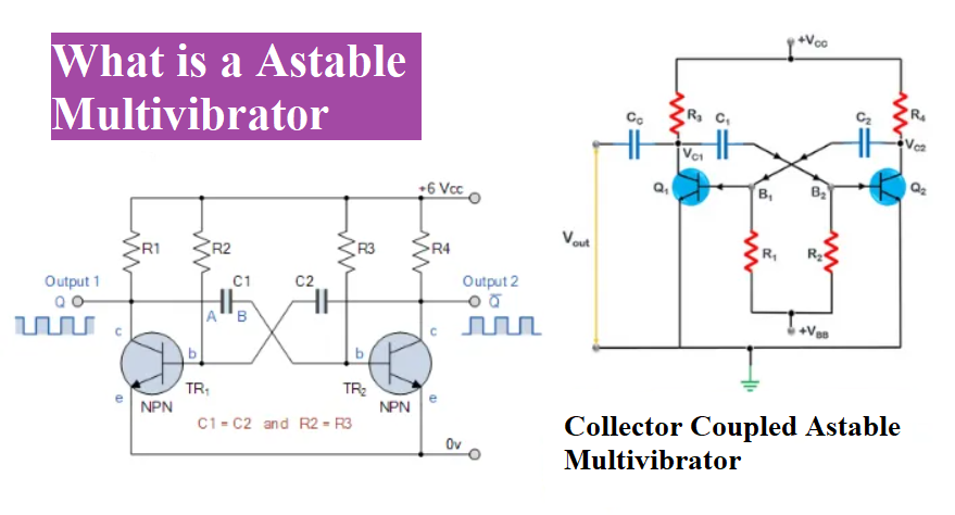
The basic principle of the Astable multivibrator is a slight variation in the electrical properties or characteristics of the transistor. This difference causes one transistor turn ON fast than the other when power is applied for the first time, thereby triggering oscillations.
The multivibrator is an electronics circuit that is use to generator non sinusoidal wave. It uses two stage of amplifier with positive feedback and the circuit is made up of both active and passive component. The active components are like transistor such as bipolar junction transistor or field effect transistor, operational amplifier Vacuum Tubes and 555 timer ICs. In this tutorial we are going to discuss about the astable multivibratior with operation using bipolar junction transistor.
The passive component is capacitors and resistors. However the designing of this circuit to ensure that the two stage of circuit continuously alter the output between cutoff and saturation regions. The multivibrator is classified in three types like astable multivibrator, monostable multivibrator and bistable multivibrator. In this tutorial we are going to discuss about the astable multivibratior with operation using bipolar junction transistor.
Astable Multivibrator
An astable multivibrator has no stable state; it means this multivibrator changes the output over a time period automatically. As a result this produces a square wave continuously at output terminal without any disturbance. The time period of square wave is determined by the RC time constants. Unlike the Monostable Multivibrator or the Bistable Multivibrator use an external triggering pulse for working but it doesn’t required any trigger pulses only required DC supply.
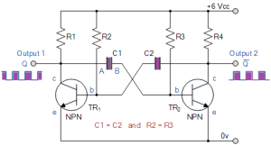
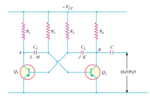
Astable Multivibrator circuit using transistor
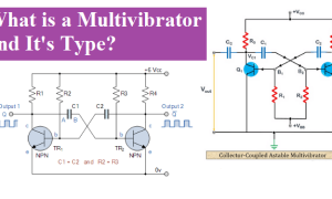
This circuit consists of two BJT transistors; a cross coupled with feedback network and two capacitors with is use for time delay between two states without any external pulse to produce the change in state. And this multivibrator is also called free running multivibrator. Because it doesn’t require any triggering pulse and produce continuously square wave.
The basic circuit is two transistors are coupled emitter terminal with ground. Both transistors are NPN or PNP and use common emitter configuration with positive feedback. This circuit configuration full fills the barkhausen criteria for oscillation i.e. βA = 1∠ 0o . This result is one transistor is in saturation and one is in cutoff region. there are mutual configuration between the two transistors.
Astable Multivibrator working
The VCC supply of circuit is 6v. The circuit connection is shown in above. Assume the transistor TR1 is cutoff and collector voltage is 6. While the transistor TR2 is in saturation conditions (turn ON position). The plate A of capacitor C1 is also rise towards 6 volt and it is connected to collector of transistor TR1 which is in cutoff region. Hence TR1 is in cutoff, the current through R1 is zero so no voltage drops across the R1 resistor. TR1

The base of transistor TR1 is connected with the plate B of the transistor C1 and at 0.6 volt the transistor TR2 is in saturation region. The potential of capacitor is +5.4 volts.
Since the TR2 is in saturation region the capacitor C2 starts to charge through resistor R2 towards the supply voltage Vcc. When the capacitor voltage reaches at 0.6, it bias transistor TR1. And the transistor TR1 starts conduction.
The TR1 is saturation and the plate A was at 6 volt, immediately falls to 0.6 volt. This rapid fall of voltage the capacitor C1 becomes -5.4v (a reverse charge). And this negative voltage turns “OFF” the transistor TR2, One unstable state.
The transistor TR2 becomes turn “OFF” so capacitor C1 start charging in the opposite direction towards +6volt via resistor R3. Thus the base of transistor TR2 is going more positive towards Vcc with a time constant C1 x R3.
However the capacitors never reach supply voltage, because when it get 0.6 volt positive transistor TR2 turns into saturation. This processes will be continue again, but capacitor C2 taking the base of transistor TR1 to -5.4v while charging up via resistor R2. The amplitude of output is almost same as Vcc and the time period is determined by the time constant of the RC networks connected across the base terminals of the transistors.
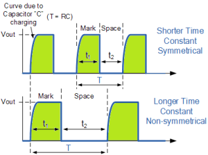
If the time constant of the circuit is produced by C1 x R3 and C2 x R2 is same in the base, the mark-to-space ratio ( t1/t2 ) will be equal to one-to-one making the output waveform symmetrical in shape. By changing R2, R3 or C1, C2 the mark-to-space ratio and therefore the frequency can be altered.
Astable Multivibrators Periodic Time
ON or OFF time -The time for one transistor may be ON or OFF is given by:
ON time for Q1 (or “OFF” time for Q2) is TR1 = 0.694 R2 C1
OFF time for Q1 (or “ON” time for Q2) is TR2 = 0.694 R3 C2
Therefore, the total time period of the square wave is T = T1+ T2 = 0.694 (R2 C1+ R3 C2)
Where the resistors R2 = R3 = R and capacitors C1 = C2 = C,
T = 0.694 (RC + RC) =1.4 RC seconds.
Frequency of the square wave is
f =1/T
=0.7/RC Hz
The resistor R is in ohms and capacitor C in farad. And this square wave is frequency is known as “Pulse Repetition Frequency”.
Astable Multivibrator Waveforms
An astable produce are two very short square wave output by two transistors or a rectangular output. The output wave may be symmetrical or non-symmetrical depending upon the time constant RC network. The output wave from are given blow:
Example 1.
In the astable multivibrator shown in Figure, R2 = R3 = 10 k Ω and C1 = C2 = 0.01 µF, Determine the time period and frequency of the square wave.
Solution. Here R = 10K Ω =104 Ω , C= 0.01 µF =10-8 F
Time period of square wave is T = 1.4 RC
= 1.4 x 104x 10-8 second
=1.4 x 10⁻⁴ second
=1.4 x 10-4 x 103 m sec
= 0.14 m sec
Frequency of the square wave is
F= (1/T in second) Hz
=(1/1.4 x 10-4 ) Hz
Frequency = 7 x 10³ Hz
= 7 kHz
Advantages of Astable Multivibrator
- It is power efficient because continually oscillate between two unstable state.
- Design of this circuit is simple.
- Low cast.
Disadvantages of Astable Multivibrator
- It does not completely provide entire output to the input due to feedback.
Applications of Astable multivibrator
- It is used in radio equipment, in timing circuits and square wave generation
People also ask
What is the function of astable multivibrator?
an astable circuit are those circuit that have no stable in either state. It mess continuously switches one state to other. This function is a relaxation oscillator.
Why astable multivibrator is called astable?
This is an electronics circuit, it is also known as Free-running Multivibrator. This circuit don’t required any external circuit to oscillate
What are the main characteristics of astable multivibrator?
An astable multivibratior is also called free running multivibrator. It has no any stable state but only two quasi stable states. It continuously is oscillating continuously without any help of external circuit. In this circuit has one transistor is ON and another is OFF
What is the state of astable multivibrator?
Astable Multivibrator Circuits is a free running multivibrator. It has two quasi states means No any permanents stable state.