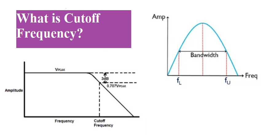
Cutoff frequency is a boundary in a system a system’s frequency response at which energy flowing through the system begins to be attenuated (reflected or reduced) rather than passing through. It is also called break frequency or corner frequency.
In an electronics system the cut-off frequency either below or above which the power output of a circuit, such as a line, amplifier, or electronic filter (e.g. a high pass filter) has fallen to a given proportion of the power in the pass band.
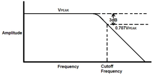
Most frequently this proportion is one-half the pass band power, also referred to as the 3 dB point since a fall of 3 dB corresponds approximately to half power. As a voltage ratio, this is a fall to approximately 0.707.
What is a filter circuit?
The filter circuits are electronics circuit that allows certain frequency and block remain frequency. The filters are various types. Here three type of filter are given below
As the name suggests itself, a low pass filter pass the low frequency signal whose range from the 0 Hz to a cutoff frequency and attenuate high frequency signal.
A high pass filter pass the high frequency signal whose range from the above the cutoff frequency and attenuate the low frequency which is below cut-off frequency.
A band pass filter pass the certain band of frequency which lie in between of high pass and low pass filters.
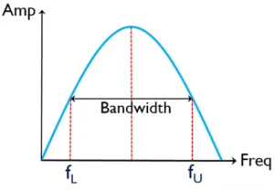
What is Bandwidth?
In signal the bandwidth is defined as the range or difference between two frequencies i.e. upper cut-off frequency and low cut-off frequency. The frequency Fu is the upper frequency and FL is a lower frequency. We can also name these two frequencies as half –Power frequencies because at this range of frequency the voltage gain drops to 70.7 % of the maximum value.
This represents the power level of one–half of the power at reference frequency in the mid-range frequency. Since the change is not noticeable, the audio amplifier has a flat response from f1 to f2.
Cutoff Frequency Formula
The formula for cut-off frequency is given below:
FC = 1/ 2πRC
Where,
R → Resistance.
C → Capacitance.
For example the cut-off (3dB point) frequency of RC low pass filter is defined as when the resistance is the same magnitude as the capacitive reactance.
Decibel unit
The gain is usually express in decibel. The unit decibel comes from logarithmic response of the human ear to intensity of sound. The decibel is defined as logarithmic measurement the ratio of output power to input power. It can also express in term of voltage.
Generally the voltage gain of amplifier is express in term of decibel. The voltage gain is given by 20log Av. The power of amplifier is also express in term of decibel (dB). The power gain is given by 10log Ap
When voltage gain Av is greater than one, we can say the gain is positive. It shows the amplification. When voltage gain Av is less than one, we can say the gain is negative. It shows the attenuation.
In amplification under few circumstances, the 0 dB gain use as reference. Which are use to compare with another value of gain.
The amplifier has maximum gain at mid frequency range and minimum at low frequency. The maximum gain is called mid frequency range gain.
How to Find Cutoff Frequency
There is various ways to find out cut-off frequency.
Cutoff Frequency from Transfer Function
Analysis of a circuit with an altering frequency of sinusoidal sources is termed as the frequency response of a circuit. The ratio of transfer functions of output to input voltage in s domain.
H(s) = Vo(s) / Vi(s)
When using a sinusoidal source, the transfer function will be given as the magnitude and phase of the output voltage to the magnitude and phase of the input. In such case jω will be use in place of “s”.
H(s) = Vo(jω) / Vi(jω)
For example, consider the transfer function
H(s) = 20(s+10) / (s+100)
To obtain the corner frequency from the above equation, H(s) can be replaced as
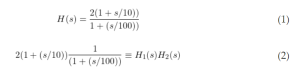
So from this equitation, the cut-off frequency ω1 is 10 rad/s and ω2 is 100 rad/s
Cutoff Frequency from Bode Plot

The above graph shows the bode plot. This graph is commonly use control system engineering for determine the stability of system. The graph plotted between phase (degree) and angular frequency (radian per second). In the bode plot, the corner frequency is the frequency at which the two asymptotes meet each other or cut each other.
The transfer function H(s) = Vo(s) / Vi(s) of a system carries extensive information of gain and stability. Bode plots give an estimated picture of a given H(s) from
Cutoff Frequency of a Low Pass Filter
The low pass filter can only allow low frequency, it cannot allow high frequency. The low pass filter have certain cut-off frequency, above the cutoff frequency the voltage drops below 70.7% of its input voltage. . The frequency, at which the magnitude response is 3 dB lower than the value at 0 Hz, is known as Cut-off Frequency of a low pass filter.
Cutoff Frequency of a High Pass Filter
The high pass filter only passes the high frequency. It blocks the low frequency below the cut-off frequency. The graph of high pass filter is shown below.

Cutoff Frequency of a Band pass Filter
The band pass filter consists of two cut-off frequencies. This filer made of low pass filter and high pass filter. The first cutoff frequency is from high pass filter is known as high cutoff frequency and second cutoff frequency is taken from low pass filter which is known as low cutoff frequency.

Frequently ask question
What is cutoff frequency in low pass filter?
The cut-off frequency is a specific frequency at which the output voltage drops by a factor of 70%. The low pass filter allows frequency in between 0 Hz to cut-off frequency. Above the cut-off frequency low pass filter attenuate the output voltage.
Why the cutoff frequency is taken at -3dB?
The decibel is a logarithmic scale expressed as 20 log(Output power/Input power). A -3 dB gain corresponds to an (Output power/Input power) ratio of 0.5, i.e., the output power of the circuit reduces by a factor of half. This serves as a standard reference for defining the boundary in the frequency response of a system.
What is meant by cutoff frequency?
The cutoff frequency is a frequency either below and above the signal are pass.
What is the formula of cutoff frequency?
The cutoff frequency is defined as the frequency where the amplitude of H(jω) is 1√2 times the DC amplitude (approximately -3dB, half power point). Solve it for ωc (cutoff angular frequency), you’ll get 1RC. Divide that by 2π and you get the cutoff frequency fc.
What is cutoff frequency in dB?
The frequency at which the magnitude response is 3 dB lower than the value at 0 Hz, is known as Cutoff Frequency of a low pass filter.
What is cutoff frequency in resonance?
A cut-off frequency refers to the frequency at which the impulse response of a filter starts to fall off. A resonant frequency refers to a frequency at which there’s a strong peak in the impulse response so that tone stands out from its neighbors. For example, think of a tuning fork.
Why is the cutoff frequency 3dB?
It’s because decibels are logarithmic, and the log (base 10) of 3 is about 50% power. So the 3 decibel cutoff is where power drops off by a half. 3 dB implies 1/2 the power and since the power is proportional to the square of voltage, the voltage will be 0,707 of the pass band voltage.