Gray code is a sequence of binary number systems, which is also known as, reflected binary code because the first N/2 values compared with those of the last N/2 values in reverse order. In gray code two consecutive values are differed by one bit of binary digits. The application of gray code is encoders, altimeters, and Karnaugh maps (K-Map) due to their error detection and unit-distant properties. In gray code the only one bit change in transition between two successive code.
What is Gray Code?
Gray code is the arrangement of binary number system such that each incremental value can only differ by one bit. This code is also known as Reflected Binary Code (RBC), Cyclic Code and Reflected Binary (RB). In gray code when transverse from one step to another step the only one bit will be change of the group. This means that the two adjacent code numbers differ from each other by only one bit.
It is popular for unit distance code but it is not use from arithmetic operations. This code has some application like convert analog to digital, error correction in digital communication.
Gray Code Table
The conversion in between decimal to gray and binary to gray code is given below:
| Decimal Number | Binary Number | Gray Code |
| 0 | 0000 | 0000 |
| 1 | 0001 | 0001 |
| 2 | 0010 | 0011 |
| 3 | 0011 | 0010 |
| 4 | 0100 | 0110 |
| 5 | 0101 | 0111 |
| 6 | 0110 | 0101 |
| 7 | 0111 | 0100 |
| 8 | 1000 | 1100 |
| 9 | 1001 | 1101 |
| 10 | 1010 | 1111 |
| 11 | 1011 | 1110 |
| 12 | 1100 | 1010 |
| 13 | 1101 | 1011 |
| 14 | 1110 | 1001 |
| 15 | 1111 | 1000 |
Converting Binary to Gray Code
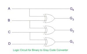
That logic circuit that converts binary to gray code is called binary to gray code converter. The binary to gray code conversion is given below;
| Binary Number | Gray Code |
| 0000 | 0000 |
| 0001 | 0001 |
| 0010 | 0011 |
| 0011 | 0010 |
| 0100 | 0110 |
| 0101 | 0111 |
| 0110 | 0101 |
| 0111 | 0100 |
| 1000 | 1100 |
| 1001 | 1101 |
| 1010 | 1111 |
How to Convert Binary to Gray Code
- The most significant bit of gray code is equal to the first bit of the given binary bit.
- The second bit of gray code will be exclusive-or (XOR) of the first and second bit of the given binary bit. i.e. if both binary bit are same the result will be “ZERO” and if both bits are different the result will be “ONE”.
- The third bit of gray code is equal to the exclusive-or (XOR) of the second and third binary bits. For father gray code result this process will be continuing.
- An example is given below to illustrate these steps.
Binary to Gray Code Conversion Example
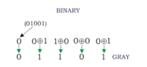
We have some binary number 010.01 which we wish to convert to gray code. Let us see the step how to convert binary to gray code?
- The first MSB bit of binary is same in the first bit of gray code. In this example the binary bit is “0”. So, gray bit also “0”.
- Next gray bit is equal to the XOR of the first and the second binary bit. The first bit is 0, and the second bit is 1. The bits are different so resultant gray bit will be “1” (second gray codes bit)
- The XOR of the second and third binary bit. The second bit is 1 and third is 0. These bits are again different so the resultant gray bit will be 1 (third gray codes bit)
- Next we perform the XOR operation on third and fourth binary bit. The third bit is 0, and the fourth bit is 0. The both bits are same than resultant gray codes will be 0 (fourth gray codes bit).
- Take the XOR of the fourth and fifth binary bit. The fourth bit is 0 and fifth bit is 1. These bits are different than resultant gray codes will be 1 (fifth gray code bit)
- The result of binary to gray codes conversion is 01101.
You can convert n bit (bnb(n-1)…b2b1b0) binary number to gray code (gng(n-1)…g2g1g0). for least significant bit bn=gn, and rest of the bit by XORing b(n-1)=g(n-1)⊕gn, …. b1=g1⊕g2⊕g3…⊕gn and b0=g0⊕g1⊕g2⊕g3…⊕gn.
K-Map for Converting Binary to Gray Code –
Let b0 b1 b2 b3 are the binary bits representation. Where binary b0 is least significant bit (LSB) and binary b3 is most significant bit (MSB). And g0 g1 g2 g3 be the bits representation of gray codes. Where g0 is the least significant bit (LSB) and g3 is the most significant bit (MSB).
The truth table for binary to gray conversion is given below:
| Binary bits | Gray bits | ||||||
| b3 | b2 | b1 | b0 | g3 | g2 | g1 | g0 |
| 0 | 0 | 0 | 0 | 0 | 0 | 0 | 0 |
| 0 | 0 | 0 | 1 | 0 | 0 | 0 | 1 |
| 0 | 0 | 1 | 0 | 0 | 0 | 1 | 1 |
| 0 | 0 | 1 | 1 | 0 | 0 | 1 | 0 |
| 0 | 1 | 0 | 0 | 0 | 1 | 1 | 0 |
| 0 | 1 | 0 | 1 | 0 | 1 | 1 | 1 |
| 0 | 1 | 1 | 0 | 0 | 1 | 0 | 1 |
| 0 | 1 | 1 | 1 | 0 | 1 | 0 | 0 |
| 1 | 0 | 0 | 0 | 1 | 1 | 0 | 0 |
| 1 | 0 | 0 | 1 | 1 | 1 | 0 | 1 |
| 1 | 0 | 1 | 0 | 1 | 1 | 1 | 1 |
| 1 | 0 | 1 | 1 | 1 | 1 | 1 | 0 |
| 1 | 1 | 0 | 0 | 1 | 0 | 1 | 0 |
| 1 | 1 | 0 | 1 | 1 | 0 | 1 | 1 |
| 1 | 1 | 1 | 0 | 1 | 0 | 0 | 1 |
| 1 | 1 | 1 | 1 | 1 | 0 | 0 | 0 |
To design the conversion of binary to gray digital logic circuit we will use the K-Map for each of the gray codes bits as output with all of the binary bits as input.
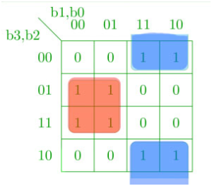
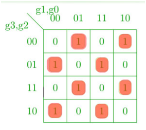
K-Map for g0 –

K-map for g1 –
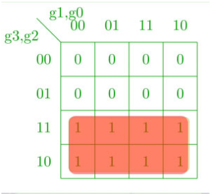
K-map for g2 –
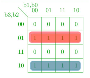
K-map for g3 –

The corresponding Boolean expression for gray codes is-

The corresponding binary to gray codes converter digital circuit is shown below –
How to convert Gray to Binary Codes
In gray to binary converter the input is gray codes and output is binary number. Let us we the four bits gray to binary converter. To design the four bits binary to gray to binary converter we first have to draw a gray codes conversion table, as shown below:
| Gray Code | Binary Number |
| 0000 | 0000 |
| 0001 | 0001 |
| 0011 | 0010 |
| 0010 | 0011 |
| 0110 | 0100 |
| 0111 | 0101 |
| 0101 | 0110 |
| 0100 | 0111 |
| 1100 | 1000 |
| 1101 | 1001 |
| 1111 | 1010 |
Gray Code to Binary Conversion
In gray to binary conversion it is simple and easy process, only we have follow some following steps;
- The most significant bit (MSB) of binary bit will be same as most significant bit (MSB) of gray code.
- Now come of second Gary code, if the second gray bit is 0, then the second binary bit will be the same as the previous or the first bit. If the gray bit is 1 the second binary bit will alter. If it was 1 it will be 0 and if it was 0 it will be 1.
- This process will continue for all bits to convert gray to binary conversion.
Below example of gray to binary conversions give will make your idea clear.

You can convert n-bit gray to (gng(n-1)…g2g1g0) to n-bit binary number (bnb(n-1)…b2b1b0) for least significant bit gn = bn and rest of the bits XORing by g(n-1)⊕ b1 b2=b0+g1(n-1) and so on.. which is shown in above figure.
Gray Code to Binary Conversion Example
- The most significant bit of gray codes is equal in binary number.
- Now move to the next gray bit, as it is 1 the previous bit will be alter i.e it will be 1, thus the second binary bit will be 1.
- Next see the third bit, in this example the third bit is 1 again, the third binary bit will be alter of second binary bit and the third binary bit will be 0.
- Now fourth bit of the, here the fourth bit of gray code is 0. So the fourth bit will be same as a previous binary bit, i.e 4th binary bit will be 0.
- The last fifth bit of gray codes is 1; the fifth binary number is altering of fourth binary number.
- Therefore the gray code (01101) equivalent in binary number is (01001)
K-Map for Converting Binary to Gray Code –
Let g0 g1 g2 g3 are the gray bits representation. Where g0 is the least significant bit (LSB) and g3 is the most significant bit. And the binary bits are b0 b1 b2 b3. Where least significant bit is b0 and most significant bit is b3.
The truth table for gray codes to binary bits conversion is given below:
| Gray code | Binary bits | ||||||
| g3 | g2 | g1 | g0 |
b3 |
b2 |
b1 |
b0 |
| 0 | 0 | 0 | 0 | 0 | 0 | 0 | 0 |
| 0 | 0 | 0 | 1 | 0 | 0 | 0 | 1 |
| 0 | 0 | 1 | 1 | 0 | 0 | 1 | 0 |
| 0 | 0 | 1 | 0 | 0 | 0 | 1 | 1 |
| 0 | 1 | 1 | 0 | 0 | 1 | 0 | 0 |
| 0 | 1 | 1 | 1 | 0 | 1 | 0 | 1 |
| 0 | 1 | 0 | 1 | 0 | 1 | 1 | 0 |
| 0 | 1 | 0 | 0 | 0 | 1 | 1 | 1 |
| 1 | 1 | 0 | 0 | 1 | 0 | 0 | 0 |
| 1 | 1 | 0 | 1 | 1 | 0 | 0 | 1 |
| 1 | 1 | 1 | 1 | 1 | 0 | 1 | 0 |
| 1 | 1 | 1 | 0 | 1 | 0 | 1 | 1 |
| 1 | 0 | 1 | 0 | 1 | 1 | 0 | 0 |
| 1 | 0 | 1 | 1 | 1 | 1 | 0 | 1 |
| 1 | 0 | 0 | 1 | 1 | 1 | 1 | 0 |
| 1 | 0 | 0 | 0 | 1 | 1 | 1 | 1 |
For design digital logic circuit of the conversion of gray code to binary bits, we will use the K-Map for each of the binary bits as output with all of the gray codes as input.
K-map for b0 –
K-map for b1 –

K-map for b2 –

K-map for b3 –
Corresponding Boolean expressions –

Corresponding digital circuit –

Application of Gray Codes
The gray codes has some specific applications, which is given below:-
- For converting analog to digital signal
- It is use for error correction in digital communication.
- It is used to minimize errors in converting analog signals to digital signals.
- Boolean circuit minimization
- Communication between clock domains
- Genetic algorithms
- Mathematical puzzles
- Position encoders
Advantages of Gray Codes
- It is best for error minimization in conversion of analog to digital signals.
- It is best for minimize a logic circuit
- Decreases the “Hamming Walls” which is undesirable state, when used in genetic algorithms
- It is useful in clock domain crossing
Disadvantages of Gray Codes
- Not suitable for arithmetic operations
- It has limited use.