A high pass filter is exactly opposite to the low pass filter, high pass filter pass the high frequency and block the low pass frequency. The circuit of high pass opposite to the low pass filters and output are taken from resistance. The filter are use to block the unwanted signal and pass the use full signal. There are various types of some types of filters are low pass, band pass and high pass filter . We already disuses the low pass and band pass. In this article we are going to discuss the high pass filter and its applications etc.
What is a High Pass Filter?
The high pass filters is electronics circuits that can pass frequencies are higher than cutoff frequencies and below cutoff frequencies attenuated. The values of cutoff frequency are defined by circuit elements.

High Pass Filter Circuit
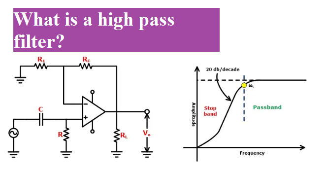
The high pass filters circuit has one capacitive element and resistive element. The circuit of high pass filters is shown below. In this arrangement the reactance of capacitor is high for low frequency so the capacitor act as a open circuit and block input signal but in high frequency the reactance of capacitor are low now the circuit act as a short circuit allowing all of the input signal to pass directly to the output as shown below in the filters response curve.

Frequency Response curve of first Order High Pass Filters
Or High Pass Filters Bode Plot
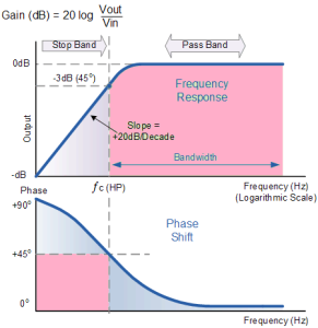
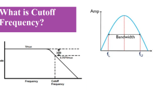
The frequency response or bode plot of high pass filter is exactly opposite to the low pass filter. From the graph which are shown above the low frequency signal are attenuated with the output increasing at +20dB/Decade until the frequency reaches the cut-off point ( ƒc ). At cutoff frequency the reactance of capacitor and resistor becomes same .i.e. R = Xc. The gain before the cutoff frequency is called stop band and above the cutoff frequency i.e. -3 dB points is known as the passband. At cutoff frequency, point output voltage amplitude will be 70.7% value or -3dB (20 log (Vout/Vin)) of the input value of the input voltage.
Gain is calculated as Gain (dB) = 20 log (Vout/Vin).
The phase angle (Φ) of high pass filter leads of input by +45o at frequency ƒc. The phase angle of high pass filter is calculated by:-
∅ = arctan (1/2πfRC)
High pass Cut-off Frequency and Phase Shift
The formula for Cut-off Frequency of high pass filter is same equation as that of the low pass filter and the formula for phase shift high pass filter is given below:

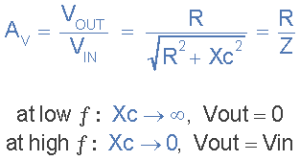
Circuit gain Av, is Vout/Vin and is calculated as:
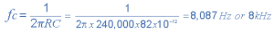
High Pass Example No1
Find out cutoff frequency ( ƒc ) of high pass consisting of an 82pF capacitor connected in series with a 240kΩ resistor.
High Pass Filter Second order
The second order high pass filter can be formed by cascading two first order filter the figure of second order filter are shown in figure.
Second order High Pass Filter circuit

The above figure show the second order of filter which is made by connecting two first order filters in series manner. Using this process the first order filter is converted into second order filter and It is also called two-pole high pass network. Due to this result a slope of 40dB/decade (12dB/octave).
The cutoff frequency of second order is calculated by as follows:-
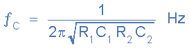
In practical, the cascading of two filter produce large order filters. However to reduce the loading effect we make the impedance of each following stage 10x the previous stage, so R2 = 10*R1 and C2 = 1/10th of C1.
High pass RC filter
A high pass filter that pass high frequency or above the cutoff frequency and attenuate the low frequency. The RC high pass is constructing with the help of resistor and capacitor. The input is applied to capacitor. The circuit diagram of high pass RC is given below.

Difference between high pass and Low pass
Low pass : The low pass is a type of filters that can pass only low frequency or below cutoff frequency. And it attenuates high frequency. It is use for smoothing the image.
High pass : The high pass are one of the types of filters that are use to attenuate the low pass and allow to high frequency, or above the cutoff frequency. It is also use for sharpening the image.
Difference between high pass and Low pass :
| Low pass | High pass |
| Smoothing image. | Sharpening image. |
| It attenuates high frequency or above cutoff frequency. | It attenuates the low frequency or below cutoff frequency. |
| Low frequency is preserved in it. | High frequency is preserved in it. |
| It allows the frequencies below cut off frequency | It allows the frequencies above cut off frequency. |
| The input applied to resistor that is followed by capacitor. | The input applied to capacitor that is followed by a resistor. |
| It is use for removal of aliasing effect. | It is use for removal of noise. |
| G(u, v) = H(u, v) . F(u, v) | H(u, v) = 1 – H'(u, v) |
Applications of High Pass
The high pass filters are use in many applications:-
- It is used in speakers for amplification.
- It is used to remove unwanted sounds near to the lower end of the audible range.
- It is used for AC-coupling.
- For Image Processing: High pass filters are used in image processing for sharpening the details.
High Pass Summary
The function of high pass filter is reverse of low pass filter. This filters attenuate signal below cutoff frequency and pass above cutoff frequency. The voltage gain at cut-off frequency is 70.7% or -3dB that allow to passes.
The frequency below the cutoff is known as stop band while above the cutoff frequency is known as pass band. The cutoff frequency are calculated by using ƒc = 1/(2πRC). The phase angle of output signal+45o at cutoff frequency (ƒc). Generally the high pass has low distortion then low pass due to the higher operating frequencies. It is commonly use in audio amplifier as a coupling between two stages of amplifiers, image processing etc.
The output voltage are depends upon the time constant and frequency of input signal. When we applied an alternating current to input side of circuit, it behaves like a simple first order high pass. But when we applied square wave to the input side of circuit, the shape of output is like a vertical step input.