JK Flip Flop: Truth Table & Timing Diagram
JK flip flop is a designed for the invalid state of SR flip flops but when both inputs is low the output will be no change. It is modified version of the SR flip flop or similar to SR flip flop. It is invented by Jack Kilby, hence the name JK flip flop.
The SR flip flop has many advantage and uses in sequential logic circuits but the drawback is two basic switching problem.
- When “SET” and “RESET” inputs are “0” condition must always be avoided
- If Set or Reset change state while the enable (EN) input is high the correct latching action may not occur.
For avoiding these two fundamental problems of SR flip flop by using JK flip flops. The simple JK flip flops are widely use in design of all the flip flops and it is considering as a universal flip flops.
What is a JK Flip Flop?
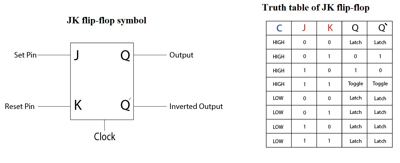
JK flip flop is example of the sequential bi-state single-bit memory device, innovated by Jack Kil. It has two inputs pin J&K and one clock pulse (CLK) and two outputs pins Q and Q̅ which is shown in figure. And the JK flip flops is triggered by positive- or negative- edge-triggered clock pulses.

Basic JK Flip-flops

The JK flip flop can be design form a SET and RESET (S&R) flip flop by using NAND gates at the input of SET and RESET, and one input of each NAND gate is connected to the output pins Q and Q̅. Another inputs of AND is named as J and K. In the above figure shows the block diagram and circuit diagram using NAND gate.
Operation and truth table
· When J and K = 0
In this input condition irrespective of the NAND inputs A & B, S’ and R’= 1, output Q =1 and Q’ = 0 and next state Q+1 = 1 Q+1’ = 0 therefore the output is no change.
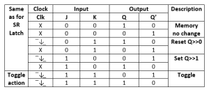
- When J = 0 and K = 1 and the output is Q = 1 & Q’ = 0 at this condition the JK flip flop is RESET.
- When J = 1 and K = 0 and the output is Q = 0 & Q’ = 1 at this condition the JK flip flop is SET.
- When J = 1 and K = 1 and the output is Q = 1 & Q’ = 0 at this condition the JK flip flop is toggled. The meaning of toggled means flip flop continuously change its SET and RESET state.
Truth Table:
Master slave flip flop
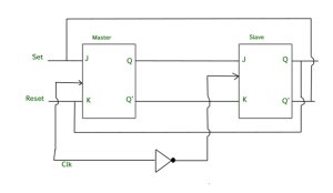
The master flip flop is the combination circuits of two flip flops are connected together in cascaded manner. Out of these two flip flop the one flip flop act as the “master” and the other as a “slave”.
The output of master is goes to slave flip flop whose output is fed back to inputs of the master flip flop.
Conversion of J-K Flip-Flop into D Flip-Flop
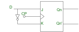
Conversion of J-K Flip-Flop into D Flip-Flop:
- Draw the truth table of D flip-flops and JK flip-flops.

- Using the K-map we find the Boolean expression of J and K in terms of D.

J = D
K = D’
- We construct the circuit diagram of the conversion of JK flip-flops into D flip-flops.
Applications of JK flip flops circuit
- It us use in sequence detector
- It is widely use in binary counter.
- JK has also use in frequency divider.
- It is use in calculating the shift register.
- It is use serial data transfer.
- It is also use in Sun Tracking Solar Panel

