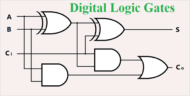
Digital Logic AND Gate
Logic gates are the electronic circuits in a digital system that are mainly based on the Boolean function. Learn about AND, OR, XOR, NOT, NAND, NOR. The Logic AND gate is the type of digital logic in which have two or more than two inputs and one output, the operation of Logic AND gate is same as the multiplication rule. The output of logic AND is HIGH “1” when all inputs are HIGH and the output is LOW “0” when any of the inputs are LOW “0”. AND gate has many number of inputs but mostly uses 2 or 3 inputs. Let us understand the output of AND behaves with respect to two inputs:
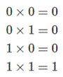
It is a simple multiplication. Here you can see if any of the inputs is low the output will be low and when both inputs are high the output is high. The Boolean expression of AND logic that of for Logical Multiplication. It is denoted by a single dot or full stop symbol, ( . ) giving us the Boolean expression of AND gate A.B = Q. where “A” and “B” is the input of AND and “Q” is the output of AND logic.
“If both inputs ‘A’ and ‘B’ are true, then ‘Q’ is true”
2 Input AND Gate
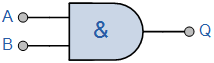
The AND logic have two inputs and one output port
AND Gate Circuit Diagram
AND Gate Diode Circuit Diagram
The AND logic circuit can be design by diode and transistor, when the diode is use in AND logic circuit called diode AND gate, which is shown in below:

The circuit diagram contains two diode inputs and one resistor. We applied power supply at “C”. When the both inputs is high the diode is reverse bias, it behaves an open circuit. The output is high. When any one of the diode input is low the low input diode is a forward bias diode and high input diode is reverse bias. The forward diode behaves like a short circuit, and due to short circuit the voltage are ground via forward bias diode and low output present at the output “X”.
2-input Transistor AND Gate
The transistor based AND gate contains two transistors and three resistors which is show in figure. The input terminal “A” and “B” and output terminal “Q”. for the high output “Q” both transistors must be saturated “ON”.

Digital Logic “AND” Gate Types
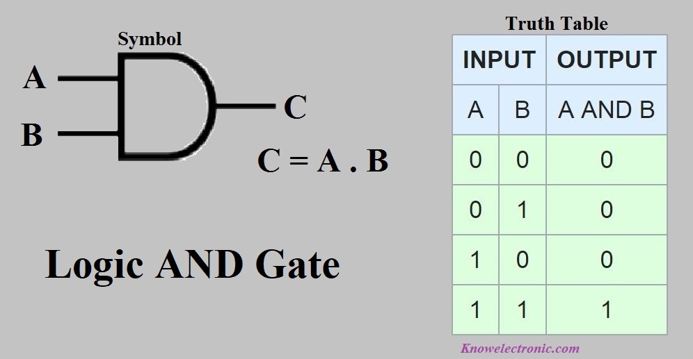
The 2-input Logic AND Gate
The two inputs AND gate having two inputs “A” and “B” and output is “Q”.
The Boolean Expression of two inputs AND logic is Q = A.B
| Symbol | Truth Table | ||
|
2-input AND Gate |
B | A | Q |
| 0 | 0 | 0 | |
| 0 | 1 | 0 | |
| 1 | 0 | 0 | |
| 1 | 1 | 1 | |
| Boolean Expression Q = A.B | Read as A AND B gives Q | ||
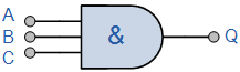
The 3-input Logic AND Gate
The three inputs AND having two inputs “A”, “B” and “C” output is “Q”.
The Boolean Expression of three inputs AND is Q = A.B.C
| Symbol | Truth Table | |||
|
3-input AND Gate |
C | B | A | Q |
| 0 | 0 | 0 | 0 | |
| 0 | 0 | 1 | 0 | |
| 0 | 1 | 0 | 0 | |
| 0 | 1 | 1 | 0 | |
| 1 | 0 | 0 | 0 | |
| 1 | 0 | 1 | 0 | |
| 1 | 1 | 0 | 0 | |
| 1 | 1 | 1 | 1 | |
| Boolean Expression Q = A.B.C | Read as A AND B AND C gives Q | |||
Multi-input AND Gate
The AND gate can be cascaded to obtained the multiple input for performing desired operation. However the commercial available AND gate IC’s having 2, 3, or 4-inputs packages. Below the figure show the cascaded AND logic;

The Boolean Expression for this 6-input AND logic will therefore be:
Q = (A.B).(C.D).(E.F)
Commonly available AND gate IC’s of TTL and CMOS technologies:
Here full list of AND gate ICs based on TTL and CMOS technologies is given below:
| S. No. | IC NUMBER | PURPOSE |
| 1. | 4073 | Triple 3 -input AND |
| 2. | 4086 | Expandable 4-wide, 2-input AND/OR invert (AOI) |
| 3. | 4085 | Dual 2 -wide, 2 -input AND/OR invert (AOI) |
| 4. | 7409 | quad 2 -input AND with open collector outputs |
| 5. | 741G08 | single 2 -input AND |
| 6. | 741G09 | single 2-input AND with open drain output |
| 7. | 7415 | triple 3-input AND with open collector outputs |
| 8. | 7450 | dual 2-wide 2-input AND-OR-invert |
| 9. | 7421 | dual 4-input AND |
| 10. | 7411 | triple 3-input AND |
| 11. | 7451 | dual 2-wide 2-input AND-OR-invert |
| 12. | 7453 | expandable 4-wide 2-input AND-OR-invert |
| 13. | 7452 | expandable 4-wide 2-input AND-OR |
| 14. | 7455 | 2-wide 4-input AND-OR-invert |
| 15. | 7453 | expandable 4-wide 2-input AND-OR-invert |
| 16. | 7454 | 4-wide 2-input AND-OR-invert |
| 17. | 7459 | 2-input and 3-input AND-OR-invert |
| 18. | 7458 | 2-input and 3-input AND-OR |
| 19. | 741G3208 | single 3 input OR-AND |
| 20. | 74808 | hex 2-input AND drivers |
| 21. | 74131 | quad 2-input AND buffer with 15 V open collector outputs |
| 22. | 74130 | quad 2-input AND buffer with 30 V open collector outputs |
Apart from these IC’s there are some for our general applications. They are listed below.
CMOS Logic AND Gates
- CD4081 Quad 2 –input
- CD4082 Dual 4 –input
- CD4073 Triple 3 –input
TTL Logic AND Gates
- 74LS08 Quad 2-input
- 74LS21 Dual 4-input
- 74LS11 Triple 3-input
7048 Quad 2-input AND Gate IC
The Quad 2-input AND 7408 IC’s is shown below;
AND gate IC 7408 is a TTL series. Inside the IC has 4 AND gate. Each pin having own function which are explained below.

Pin number detail of IC 7048
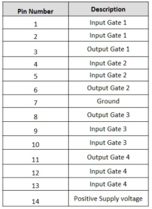
Pin 14 is supplied voltage pin. The maximum applied voltage is 5 volt DC; if we increase the supply voltage the IC may get damage.
4081 Quad 2-input AND Gate IC
The IC 4081 Quad 2-input AND is based on CMOS (complementary MOSFET). It has also 4 AND gate inside the IC. Now discuss the internal pin diagram of AND gate IC 4081:

Pin number detail of CMOS 4081 AND logic IC:

Pin 14 is supplied voltage pin. The maximum applied voltage is 5 volt DC; if we increase the supply voltage the CMOS IC 4081 may get damage.
AND gate Applications
There is a many application of AND logic in day to day life. Some applications are given below:
- It use in enable and disable purpose on counter device
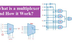
- It is using in multiplexing of signal
- It is uses in computer and communication system.
- The logic AND is used in some sort of security devices like garden flood-lights and security lights etc.
Also read: Digital Logic Gates, Multiplexer,