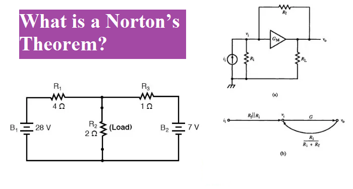
The Nortons theorem is a circuit analysis theorem use to change any complex network into a simple equivalent circuit that consists of single resistance in parallel with current source.
The Nortons theorem on the other hand the circuit reduces a single resistance in parallel with single current source. In this tutorial we are going to discuss the concept of Norton theorem with example.

What is Nortons theorem?
It is state that “ Any linear network and complex that contain many voltage and resistive element can be replace with a simple circuit that have a constant current source in parallel with a Single Resistor“.
The Norton’s theorem is just a current source transformation of Thevenin’s theorem and dual with Thevenin’s theorem.
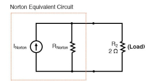
Nortons equivalent circuit diagram
The Norton circuit contain the load resistance RL is concerned this single resistance RS the value of RS measure from the terminal A and B by short circuit the voltage source and open for current source, (the same as Thevenin).

Simplifying linear circuits
Let us understand the theorem, in below circuit consist of the voltage source and more than two resistances.
After conversion into Norton
In above circuit that contain current source whose provide a constant amount of current, outputting as much or as little voltage necessary to maintain that constant current.
Thevenins theorem vs Nortons theorem
In Thevenin’s theorem “Any linear and complex circuit that contain many voltage sources or resistances are replace with simple circuit. And that simple circuit have single voltage source in series with single resistance” and in Norton theorem’s we find out the equivalent current source (INorton) and equivalent resistance (RNorton).
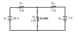
Identify the load resistance

In Norton theorem firstly we identify the load and remove the load from the circuit diagram
Find the Nortons current
After that we find the Norton current (for the current source in the Norton equivalent circuit) by short circuit connection to load and find out the current. Note that this staple is exactly opposite to the Thevenin’s Theorem, where we replaced the load resistor with a break (open circuit):

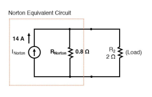
There is no voltage drop across the load, the current through R1 is strictly a function of B1‘s voltage and R1‘s resistance: 7 amps (I=E/R) and the current through R3 is now strictly a function of B2‘s voltage and R3‘s resistance: 7 amps (I=E/R). The total current through short circuit branch through short circuit branch:
IR1 + IR2 = 7 Amp +7 Amp
= 14 Amp
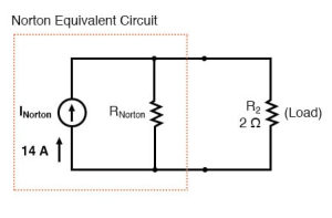
The 14 Amp becomes the Norton current and shown in above figure
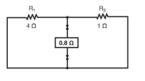
Find Nortons resistance
For finding the Norton resistance we do exactly same thing as we did for calculating Thevenin resistance Rth. Take the original circuit, short circuit voltage source and open circuit the current source. Calculate the equivalent resistance across the load. And figure total resistance from one load connection point to the other:
The final Norton equivalent circuit looks like this:
Determine the voltage across the load resistor
For finding the voltage across the load resistance we reconnect our original resistance 2 Ω, and analysis the circuit as a simple circuit.

Another example of Nortons theorem:
Find out the Norton equivalent circuit.
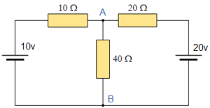
For Find out the Norton equivalent of the above circuit, firstly we remove the load resistor 40Ω and terminals A and B to give us the following circuit.

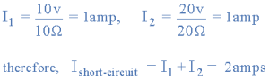
When the terminal A and B is short circuit the two resistances is 10 Ω and 20 Ω are parallel across their two respective voltage sources. And the current through each resistor as well as the total short circuit current can now be calculated as:
with A-B Shorted Out
The two voltage source are short circuited and open A and B terminal. The two resistances are now effetely connected in parallel. The total resistance calculated across the A and B terminal.

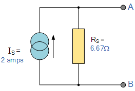
Find the Equivalent Resistance (Rs)

Now draw the Norton from the Norton equivalent circuit, connecting the current source in parallel with equivalent resistance.
Nortons equivalent circuit
Now we connect the load 40Ω across the A and B terminal.

Again, the two resistors are connected in parallel and calculate the total resistance.

Calculate the voltage across the terminal A and B with load resistor connected is given as:
![]()
Then the current flowing in the 40Ω load resistor can be found as:

Nortons Theorem Summary
The basic procedure for solving a circuit using Norton’s Theorem is as follows:
- Remove the load resistor RL.
- Find Rn by shorting all voltage sources or by open circuiting all the current sources.
- Find In by placing a shorting link on the output terminals A and B.
- Find the current flowing through the load resistor RL.