A resistance is an electrical component and the resistors in series are controls the flow of electric voltage in an electrical circuit. Also we can use to control the voltage or specific voltage to operate the some sensitive device, which is damage by over electrical voltage. The current through the resistor is directly proportion to the voltage and inversely proportional to the resistance. When we said the resistance in series connection it means they are connected to daisy chained together in straight line with common current flow in straight line.
Resistors in a Series connection
When the resister is in series connection it means the resister is in daisy-chained together in a single line. Subsequently, the current flowing through the first resistor than second and so on because in series connection there is no another way to pass the current. In a series connection of resistance they are no current divided. A resister can be use to convert voltage source to current source and the current source to voltage source. In an electric circuit the complex combination of resister can be replaced by the one single equivalent resistance REQ or impedance, ZEQ and no matter which type of combination of the resistor network, all resistors follow the basic rule of electric i.e. Ohm’s Law and Kirchhoff’s Circuit Laws.
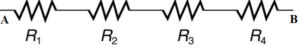
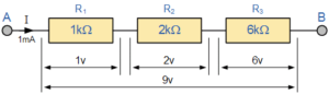
IR1 = IR2 = IR3 =IR4 = IAB = 1mA
The above is the example of R1, R2, R3 and R4 are all connected in series between points A and B with common current 1 mA follow.
 The above figure show the circuit of resistance in series which is connected to the voltage “V”. The total resistance of the circuit is the individual sum of the resistance, which is RT = R1 + R2 + R3
How to Calculate Voltage Changes in Resistors in Series Using Ohm ‘s Law
According to Ohm’s law the current through the resistance is directly proportional to the voltage and inversely proportional to the resistance the voltage in a circuit is V=IR, where I is current and R is the resistance.
Now, we are calculating the individual voltage drop across the individual resistance R1, R2 and R3. The voltage drop across the R1 is V1=IR1, across R2 is V2=IR2, and across R3 is V3=IR3. The sum of total voltage is equal to the VT = V1 + V2 + V3.
V = IR3 + IR3 + IR3
or
V = I (R3 + R3 + R3)
Now we have to convert the individual resistance in an equivalent single resistance Rs, we have
V=IRs
IRs = I (R3 + R3 + R3)
So, Rs = R3 + R3 + R3
For “N” number of resistance the total resistance will be:
Rs = R1 + R2 + R3 +………………..+ RN.
Series Resistor Circuit

The above circuit diagram there is three resistances R1 R2 R3 and it is connected in series between the point A and B, with a common current “I” and the total resistance is RT of the circuit is equal to the sum of the individual resistance added together. That is:
RT = R1 + R2 + R3
The mathematical value of the above circuit diagram is
RT = 1kΩ + 2kΩ + 6kΩ = 9kΩ
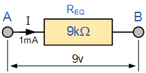
Now the above figure shoes the replace all three resistance with the single resistance which is 9kΩ.
Series Resistor Equation
Rs = R3 + R3 + R3 +………………..+ RN.
Note that the equivalent resistance is the algebraic sum of all individual resistance.
Series Resistor Voltage
In a series connection of resistance the voltage drop across the individual resistance is different. We have already see the total voltage drop is equal to the individual sum of the voltage drop across R1, R2 and R3 , VAB = VR1 + VR2 + VR3 = 9V.
According to the Ohm’s Law, the voltage across individual resistors is :
Voltage V1 = IR1
= 1mA x 1kΩ = 1V
Voltage V2 = IR2
= 1mA x 2kΩ = 2V
Voltage V3 = IR3
= 1mA x 6kΩ = 6V
The sum of the voltage across the resistors is equal to the total voltage across the combination of all resistance this is 9V. The total voltage in a series circuit is the algebraic sum of all the individual voltages is given as:
VT = V1 + V2 + V3.
Resistors in Series Example No1
The figure show the resistance and voltage circuit with proper value calculate the equivalent series resistance, series current, voltage drop and power for each resistor,
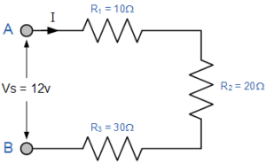
All the date in tabular form given below:
| Resistance | Voltage | Current | Power |
| R1 = 10Ω | 2V | 200mA | 0.4W |
| R2 = 20Ω | 4V | 200mA | 0.8W |
| R3 = 30Ω | 6V | 200mA | 1.2W |
| RT = 60Ω | 12V | 200mA | 2.4W |
For the circuit above,
- Total resistance RT = 60Ω,
- Total current IT = 200mA,
- Total voltage VS = 12V
- Total power PT = 2.4W
The Voltage Divider Circuit
From the above example the supply voltage is 12 volt and all resistor are connected in series with a single supply DC voltage, different voltage appear across the individual resistance producing a circuit called a Voltage Divider.
In voltage divider network, the voltage is directly proportional to across each resistor in the series chain with the amount of voltage drop being determined by the resistors value. The current through all the resistance will be same and the large resistance drop large voltage drop and small resistance drop small resistance. The voltage divider circuit is given below:
Voltage Divider Network

The above circuit show the voltage divide. In this circuit diagram there are two resistance R1 and R2 are connected together in series and the supply voltage is Vin and output voltage is Vout is taken from across resistor R2. The output voltage is calculated by given formula which is given below:
Vout = Vin (R2 / R1 + R2)
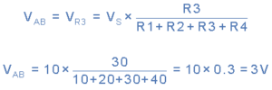
If more resisters are connected in series have different voltage appear on the individual resistance. So, if we had three or more resistances in the series connection, we can still use our now voltage divider formula to find the voltage drops across each one. The circuit is given below.

The voltage divider circuit above shows with four resistances connected in series. The voltage drop across points A and B can be calculated using the voltage divider formula as below:
Resistors in Series Example No2
Find the voltage between X and Y
(a) Without RL connected
(b) With RL connected

Applications
The applications of series resistance are give below
- Resistors in series are used to as a voltage divider network.
- Used as Light dependent resistor (LDR) for light sensing application.
- In thermistor (Positive temperature coefficient) temperature measurement and control unit.
Resistors in Series Summary
When two or more than two resistance are connected together in daisy chain in a single branch, the resistor are said to be connected together in series. In series connection of resistance is carry the same current it means there is no divider of current in circuit only division of voltage across the individual resistance because the value of resistance is differ. The voltage across the individual resistor is determine by using Ohm’s Law (V = I*R). Then the series circuit is called voltage divider network.
In a series connection of network the sum of individual resistance is equal to the equivalent resistance, (RT ) of the series combination. The series resistance can be easily interchange the resistance without affecting the equivalent resistance, (RT), current, or power to each resistor or the circuit.
Frequently asked questions
How do you calculate resistors in series?
In any the electrical circuit the resistor is connected in series, we can replace all the individual resistance by and equivalent resistance Req and calculate the equivalent resistance by given formula which is given
Req = R1 + R2 + R3 +………………..+ RN.
What happens when resistors are connected in series?
When we connect the two or more than two resistance in daisy chain is called series resistance. It divides the voltage to protect our sensitive electrical equipment
What is the purpose of a series resistor?
The purpose of series resistor to
- Voltage divider network.
- Light sensing application.
- Temperature measurement and control unit.
Can you use two resistors in series?
Yes, we can use two resistor in series circuit to form a resistor in series the formula of combination of to resistance is : Req = R1 + R2 in
Also read:- Half Wave Rectifier, Zener Diode.