A bistable multivibratior is a one of the type of multlivibratior circuit. A bistable multivibrator circuit has two stable states i.e. high and low. The state will be same until and unless an external trigger input is applied.
Generally this circuit stays high until a trigger pulse is not applied, if when the trigger pulse is applied, it changes the output state. Bistable multivibratior is also known as flip flop or latches because the flip flop behave same operation like bistable multivibratior. This is also called binary or flip flop circuit.
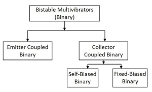
There are few types in Bistable Multivibrators, which are shown below in figure from.
The collector coupled further divide in two types
What is a Bistable Multivibrator?
A bistable is the one of the type of multivibratior device similar to the monostable, we discus about monostable in previous article but the difference this time is that BOTH states are stable.
It has two stable states and maintains the state until the external trigger is not applied. This means the output will be shifted from one stage to another stage by applying trigger pulse. It required two external pulses to return original state. As it has two stable stages they are known as latches and flip flop.
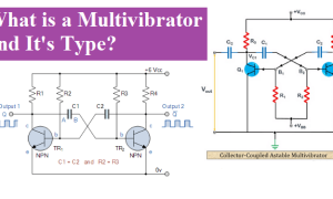
Bistable Multivibrator Circuit diagram
The bistable multivibrator has two state non-regenerative devices. The circuit configuration is a cross coupling of two transistors one is in ON and OFF switching. That means one transistor is in cut-off region and other transistor is in saturation region. The bistable circuit is capable in either stable state without trigger pulse.
To change the stage from one stable state to another state it required external trigger pulse; when we applied two trigger pulses to bistable circuit it return to original position. It is also known as flip flop or latch circuit. The circuit diagram is shown below.

Bistable Multivibrator Operation
The circuit diagram of bistable is shown above is stable in both state. In this circuit shows two transistors, one transistor is in cut off region and other in saturation region. Let’s suppose the base of transistor TR1 is connected to the ground which is shown in figure, and it is cut off region producing output at Q. That would mean that transistor TR2 is saturation region. The base of transistor TR2 is connected to Vcc with the series combination of R1 & R2. As transistor TR2 is “ON” there will be zero output at Q, the opposite or inverse of Q.
Now if we applied a trigger pulse at point “B”. the transistor TR2 will switch “OFF” and transistor TR1 will switch “ON” through the combination of resistors R3 and R4 resulting in an output at Q and zero output at Q the reverse of above. Then we can say that the stable state exist when TR1 is ON and TR2 is OFF, switching position A. and other stable state is exist, TR2 is ON and TR1 is OFF, switching position B.
In monostable multivibrator whose output is dependent on the RC time constant with feedback but in bistable the output is depend on the applications of two individual trigger with changing switching position from A to B.
Bistable Multivibrator output Waveform
The bistable multivibrator waveform depends upon the output of transistors. The leading edge of waveform depends on applied trigger pulse and trailing edge is on second trigger this is shown in figure.

Manually switching pulse between state produce bistable multivibrator circuit, and it is not practically possible. So we use trigger circuit for trigging.
Advantages
The advantages of bistable Multivibrator are given below
- Stores the previous output unless disturbed.
- Its circuit design is easy and simple
Disadvantages
The disadvantage are given below
- It requied two trigger pulses.
- A bit costlier than other Multivibrators.
Applications
Bistable Multivibrators are used in applications such as pulse generation and digital operations like counting, flip flop and storing of binary information.
People also ask
What is bistable multivibrator?
The bistable multivibrator is an electronics circuit, it has two stable states. It can change state from one state to another state by applying external trigger pulse. It is also known as flip flop and latch. It is use in digital computer for store binary bits.
Where is bistable multivibrator used?
The bistable is motley use in digital communication, counter and reversing to the supply to a given circuit at regular intervals.
What are the types of bistable multivibrator?
There are three types of multivibrator monostable, astable, and bistable. The bistable multivibrator is a pulse detector, when it detects pulse it changes the states from high to low or low to high. There are few types in Bistable Multivibrators, which are shown below.
- Emitter coupled binary
- Collector coupled binary
The collector coupled further divide in two types
- Self biased binary
- Fixed biased binary
Why is it called bistable multivibrator?
The bistable multivibratior has two states and both states are stable without trigger pulse. The word “BI” means two.
What is bistable explain?
A bistable multivibrator is two stable states. This circuit stays in any one stable state when no external trigger is applied it. The trigger pulse changes its state. Bistable multivibrator is also called flip flop.
What is an advantage and disadvantage of bistable multivibrator?
The advantage is Stores the previous output unless disturbed and circuit design is easy and simple. Disadvantage is required two pulses for change stage from high to low or low to high.