What is slew rate of operational amplifier? In this article we are going to study of what is slew rate of operational amplifier and contrast it to the concept of bandwidth. Firstly we differentiate between real and ideal operational amplifier. Through this differentiation we can easily understand how slew rate can cause difference between real and ideal operational amplifier.

A SR of Op-amp is critical factors that determine the overall performance of electronics circuit. In this article we are going to study of what is SR and how to calculate SR for Op-amp, the effect of sinusoidal wave and triangular wave and its use advantage and disadvantage.
The slew rate is the key of most electronics circuit. The slew rate determines the circuit accommodates fast output rises & reduces distortion.
What is Slew Rate?
The SR is the maximum rate of output voltage is changes with respect to time. In other word, that described the rate of variation of output voltage per unit time. The denotation of SR is “S”. The SR determine the amplitude and maximum input frequency suitable to an operational amplifier (OP-amp) such that the output is not significantly distorted. If the SR is high the signal is less distorted and when the SR is low that produce high distorted signal.
It is a critical factor that decides the operation amplifier can deliver an output that is reliable to the input. The SR is changes with the voltage gain change. Therefore, it is generally specified at unity (+1) gain condition. A typically general-purpose device may have a SR of 10 V/µs. the SR 10 V/µs is shows the when large step input signal is applied at the input terminal of op-amp provides an output of 10 volt in 1 microsecond time. In a certain application where the speed is required and the quickly changes the output, the SR is the operational amplifier can have a significant effect on the electronics circuit overall performance, and the design needs to accommodate this.
Slew rate unit
The unit of SR is V/µsec (Volts/microsecond). Let us see the example – if the device has 10 V/ µsec, this means the voltage can be changes by 10 volt in 1 μs. It is measure by applying large voltage signal to the operational amplifier and the rate of change of output voltage signal amplitude from 10 % to 90 % is measured. It is proportional to temperature i.e. when the temperature increase the SR is increase. That amplifier has high SR consume high current.
Slew Rate Formula & calculation
The formula for the SR calculation is given by
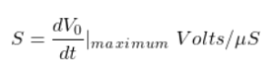
Where V0 is the output produced by the amplifier as a function of time t. The another formula to calculate the SR of an amplifier, the maximum voltage and frequency required. For a distortion free operation, the simple formula can be use SR = 2 π f V
Where
SR is measured in volts / second or v/µs,
- f is the highest signal frequency in Hz
- V is the maximum peak voltage of the output signal.
As an example, where an op amp is required to amplify a signal with peak amplitude of 5 volts at a frequency of 25 kHz.
SR =2 π f V
=2 π x 25 000 x 5
= 0.785V/µs (would be required).
How to Measure Slew Rate?
When the step input signal is applied at the input stage of op-amp and the SR is measure the amplitude changes from 10% to 90% of the output signal. The SR is measured from the output voltage signal as

The instruments are uses to measure of SR are oscilloscope and a function generator. Below the circuit how to measure the SR using CRO.

The exact output graph of SR limited is given below.

Slew Rate of OP Amp 741
How fast the output is change the operational amplifier is decided by SR. Hence it shows the highest frequency of the operation of the given op-amp. The SR limits the performance of op-amp. The op-amp may have a different SR and it is depends upon circuit configuration. Ideal the SR is infinite but in practically as high as possible. The slew rate of IC 741 op-amp is only about 0.5 V/µsec (Volts/microsecond). It is major drawback. It limits the high frequency application.
Slew Rate of Ideal Op-Amp
In ideal op-amp the time delay is zero. According to the equation,

The above equation show the SR of ideal op-amp is infinite.
Slew rate of different amplifier
The given table shows different type of op-amp slew rate value

Temperature:
Slew rate is a temperature dependent quantity. This means when temperature increase positive SR occurs and when temperature fall negative SR occurs. SR is directly proportional to temperature.
Applications of Slew Rate
The advantages include:
- It is use to find out input frequency and amplitude of the Amplifier.
- It removes distortion in output signal.
- When SR high gives better reproduced signal.
- Very fast SR Op-amps require low impedance power supply.
Disadvantages of Slew Rate
- If the SR exceeds, the output waveform is distorted.
People also ask
How is op-amp slew calculated?
The SR is calculated by step input signal applied at the input state of op-amp and observed the rate of change of output signal from 10% to 90% of the signal amplitude. Generally the value of step signal value is 1 V.
What is the formula of slew ?
The another formula of slew is 2πfV =2(3.14)(f)(0.5V), the IC LM741output is 0.5 V and frequency is 159,235 Hz. At 79,617 Hz frequency the output voltage of LM 741 is 1 V. this is use for converting from the time from μS to S, we can measure the frequency from the SR formula 2πfV
What is meant by slew ?
The definition of SR is the change of voltage and current or any other electrical parameter with respect to per unit time. And the unit of SR is amperes/second or volts/second but it is expressed in microseconds (μs)
What is a good slew?
The common values of most of the amplifier have a SR above 6.3 V/µs. it shows the good for amplifier. This high value of SR eliminates any potential errors and unwanted distortion whatsoever.
What causes slew?
The SR is maximum change of output voltage amplitude from 10% to 90% with respect to time. The SR belongs to the category of large signal phenomenon, current limiting and the saturation of intrinsic stages of op-amp leads to reasons of SR to greater extent.
What is high slew rate amplifier?
Slew is maximum change of output voltage of current with respect to per unit time (measured in Volts per microsecond). For high power amplifier slew obtain same power bandwidth.
What is slew rate and CMRR in op-amp?
The ideal op-amp amplifiers amplify the input signal without any distortion. The common mode rejection of ideal op-amp is infinity and SR is also infinity because the value of time is “zero”.
Why is the slew rate so high?
Suppose the input signal switches speedily and the value of slew rate is low. This means show the output voltage cannot change at the rate of input signal. So SR must be high. So that op-amp can change output signal with input signal.
What is slew rate of a sine wave?
The frequency of sine wave if f Hz and maximum voltage is V the required SR of operational amplifier is 2 x Π x f x V volts per second. This shows the zero crossing point can be met.
Which op amp has high slew rate?
The LT1357 op-amp has a high SR
What do you mean by CMRR and slew rate?
Common mode rejection ratio (CMRR) is the ration of differential mode gain to common mode gain. And the slew rate is maximum change of output voltage with respect to per unit time.
also read- Digital to analog converter, Passive low pass filter, Hamming code, Full wave rectifier.